Synchronous Motor Working Principle
Electrical motor in general is an electro-mechanical device that converts energy from electrical domain to mechanical domain. Based on the type of input we have classified it into single phase and 3 phase motors. Among 3 phase motors, induction motors and synchronous motors are more widely used. When a 3 phase electric conductors are placed in a certain geometrical positions (In certain angle from one another) then an electrical field is generated. Now the rotating magnetic field rotates at a certain speed, that speed is called synchronous speed. Now if an electromagnet is present in this rotating magnetic field, the electromagnet is magnetically locked with this rotating magnetic field and rotates with same speed of rotating field.Synchronous motors is called so because the speed of the rotor of this motor is same as the rotating magnetic field. It is basically a fixed speed motor because it has only one speed, which is synchronous speed and therefore no intermediate speed is there or in other words it’s in synchronism with the supply frequency. Synchronous speed is given byWhere, f = supply frequency and p = no. of poles

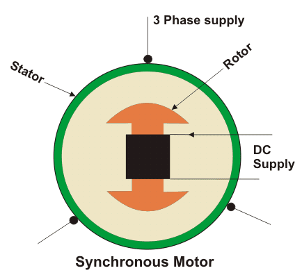
Construction of Synchronous Motor
 Normally it's construction is almost similar to that of a 3 phase induction motor, except the fact that the rotor is given DC supply, the reason of which is explained later. Now, let us first go through the basic construction of this type of motor.
From the above picture, it is clear that how this type of motors are designed. The stator is given is given three phase supply and the rotor is given DC supply.
Main Features of Synchronous Motors
- Synchronous motors are inherently not self starting. They require some external means to bring their speed close to synchronous speed to before they are synchronized.
- The speed of operation of is in synchronism with the supply frequency and hence for constant supply frequency they behave as constant speed motor irrespective of load condition
- This motor has the unique characteristics of operating under any electrical power factor. This makes it being used in electrical power factor improvement.
Principle of Operation Synchronous Motor
Synchronous motor is a doubly excited machine i.e two electrical inputs are provided to it. It’s stator winding which consists of a 3 phase winding is provided with 3 phase supply and rotor is provided with DC supply. The 3 phase stator winding carrying 3 phase currents produces 3 phase rotating magnetic flux. The rotor carrying DC supply also produces a constant flux. Considering the frequency to be 50 Hz, from the above relation we can see that the 3 phase rotating flux rotates about 3000 revolution in 1 min or 50 revolutions in 1 sec. At a particular instant rotor and stator poles might be of same polarity (N-N or S-S) causing repulsive force on rotor and the very next second it will be N-S causing attractive force. But due to inertia of the rotor, it is unable to rotate in any direction due to attractive or repulsive force and remain in standstill condition. Hence it is not self starting.
To overcome this inertia, rotor is initially fed some mechanical input which rotates it in same direction as magnetic field to a speed very close to synchronous speed. After some time magnetic locking occurs and the synchronous motor rotates in synchronism with the frequency.
To overcome this inertia, rotor is initially fed some mechanical input which rotates it in same direction as magnetic field to a speed very close to synchronous speed. After some time magnetic locking occurs and the synchronous motor rotates in synchronism with the frequency.
-------------------------------------------------------------------------------------------------------------
AC series motors are also known as the modified DC series motor as their construction is very similar to that of the DC series motor. Before we discuss these modifications, here it is essential to discuss what is the need and where do we need to do modifications. In order to understand this, consider this question. What will happen when we give an AC supply to DC series motor? Answer to this question is written below:
What about power factor how we can improve power factor? Now the power factor is directly related to reactance of the field and armature circuit and we can reduce the field winding reactance by reducing the number of turns in the field winding. But there is one problem: on reducing the number of turns, field mmf will decrease and due to this the air gap flux decrease. The overall result of this is that there is an increase in the speed of the motor but decrease in the motor torque which is not desired. Now how to overcome this problem? The solution to this problem is the use of compensating winding. On the basis of the usage of compensating winding we have two types of motor and they are written below:
- An AC supply will produce an unidirectional torque because the direction of both the currents (i.e. armature current and field current) reverses at the same time.
- Due to presence of alternating current, eddy currents are induced in the yoke and field cores which results in excessive heating of the yoke and field cores.
- Due to the high inductance of the field and the armature circuit, the power factor would become very low.
- There is sparking at the brushes of the DC series motor.
What about power factor how we can improve power factor? Now the power factor is directly related to reactance of the field and armature circuit and we can reduce the field winding reactance by reducing the number of turns in the field winding. But there is one problem: on reducing the number of turns, field mmf will decrease and due to this the air gap flux decrease. The overall result of this is that there is an increase in the speed of the motor but decrease in the motor torque which is not desired. Now how to overcome this problem? The solution to this problem is the use of compensating winding. On the basis of the usage of compensating winding we have two types of motor and they are written below:
- Conductively compensated type of motors.
- Inductively compensated type of motors.
Conductively Compensated Type of Motors
Given below is the circuit diagram of the conductively compensated type of motors. In this type of motor, the compensating winding is connected in series with the armature circuit. The winding is put in the stator slots. The axis of the compensating winding is 90o (electrical) with main field axis.
Inductively Compensated Type of Motors
Given below is the circuit diagram of the inductively compensated type of motors. In this type of motor, the compensating winding has no interconnection with the armature circuit of the motor. In this case, a transformeraction will take place as the armature winding will act as primary winding of the transformer and the compensation winding will acts as a secondary winding. The current in the compensating winding will be in phase opposition to the current in the armature winding. Given below is the complete schematic diagram of the single phase AC series motor with all the modifications (i.e. compensating winding and inter pole)
Nice article bro…But this is How VFD Saves Power & Basic Concept of VFDis useful in such a way that it saves an alternating current. Current transformer is useful in such a way that it produces an alternating current in its secondary winding which is proportional to the current measured in its primary winding. Thanks for sharing this post..Very use full information about electrical.. Also can you explain about below mentioned article. about electrical power system protection on Transformer Protection and Read more details about Power system protection
ReplyDelete